Who builds these? Primarily in-house engineering teams at logistics companies, IoT developers prototyping fleet products, and fleet tech teams moving from off-the-shelf tools to custom infrastructure. The gap between a working prototype and a production-grade deployment is significant, and most of the failure points are architectural, not mechanical.
This guide covers the full project: core components, system architecture, a step-by-step build process, testing methodology, and the most common problems you'll encounter in real deployments.
Key Takeaways
- A complete tracking system requires three layers: hardware (GPS + cellular modem), communication (MQTT or WebSocket), and software (backend server, spatial database, and map frontend)
- Most build failures happen at the communication layer — polling instead of persistent connections causes lag and data loss
- Production systems need geofencing, trip history, and offline buffering from day one
- Always run structured field tests before fleet-wide deployment; validate GPS accuracy, pipeline latency, and alert triggers
Core Components of a Real-Time Vehicle Tracking System
Every real-time vehicle tracking system has three interdependent layers. A precise GPS module paired with an undersized backend still produces a broken experience — each layer depends on the others performing.
Hardware Layer
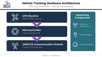
The GPS receiver is the foundation. It acquires satellite signals and outputs latitude, longitude, speed, and heading data — outputting data in NMEA 0183 format, the serial ASCII protocol GPS modules have used for decades. According to GPS.gov, standard GPS accuracy is committed to 7.8 meters horizontal at 95% confidence under specified conditions. Receivers with WAAS support can achieve positional accuracy of a few meters by using ground-based and space-based augmentation networks — a meaningful improvement for fleet applications.
The microcontroller or control unit reads GPS data, applies logic, and routes it to the communication module. For prototypes, Arduino or Raspberry Pi work well. Production fleet deployments typically use dedicated OBD-II or hardwired telematics units, which are more rugged and require no custom firmware.
Supporting hardware matters too:
- Antenna placement — mount with a clear view of the sky; obstructions degrade signal lock time and accuracy
- Power supply — vehicle battery tap is standard for permanent installs; internal batteries suit trailer or asset tracking
- Accelerometers — optional sensors that enable driver behavior monitoring (harsh braking, rapid acceleration) at the device level
Software Layer
That hardware stack only delivers value when the software layer processes and surfaces the data reliably.
The backend server ingests location pings, stores them in a time-series-capable database, and serves data to the frontend. PostgreSQL with PostGIS spatial indexing handles most fleet-scale deployments well. InfluxDB is an alternative built specifically for high-volume timestamped data, which suits IoT telemetry workloads.
The frontend map interface renders live vehicle positions, geofence overlays, and trip history polylines. This is where mapping API costs become a real concern at scale. Google Maps Platform bills per billable event — Dynamic Maps starts at $7.00 per 1,000 events, and Compute Routes starts at $5.00 per 1,000 events, with free caps that are small relative to high-frequency fleet updates.
For production fleets, per-call billing compounds quickly. A dashboard refreshing every few seconds across hundreds of vehicles can generate tens of thousands of billable events per hour. Platforms like NextBillion.ai offer fleet-grade mapping APIs with per-vehicle or fixed monthly pricing, which removes that variable entirely. The best real-time tracker for a given fleet is less about a single device and more about this full stack working together — accurate hardware, a persistent low-overhead protocol, and a mapping layer priced for continuous fleet-scale use, rather than per-event consumer pricing.
System Architecture and Communication Design
Architecture defines how data flows from vehicle to screen. The wrong protocol decision is the single most common source of high latency, dropped updates, and excessive data costs.
Communication Protocols
Two protocols dominate real-time fleet tracking:
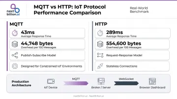
MQTT (Message Queuing Telemetry Transport) is an OASIS Standard designed for constrained IoT environments with limited bandwidth. Its publish-subscribe model minimizes overhead per message — critical when devices transmit location pings every few seconds.
A HiveMQ benchmark quantifies the difference: 43 ms average MQTT response time versus 289 ms for HTTP across 100 messages, with 44,748 bytes of MQTT overhead versus 554,600 bytes for HTTP at the same volume. Use MQTT for device-to-server communication.
WebSocket (defined in RFC 6455) maintains a persistent bidirectional TCP connection between server and browser. It eliminates the repeated HTTP header overhead that polling creates. Use WebSocket for server-to-dashboard connections.
Most production systems use both: MQTT from device to broker, WebSocket from server to browser. This layered design is also part of why a vehicle can be tracked without the occupant's direct awareness — the device transmits pings automatically in the background over the cellular network, independent of any app open on a phone, which is why detecting an unknown tracker generally requires a physical inspection of the vehicle rather than relying on phone-based scanning.
Message brokers distribute location updates to multiple consumers simultaneously:
- Redis Pub/Sub — at-most-once delivery, non-persistent; ideal for transient dashboard fan-out
- Apache Kafka — durable, replayable event storage; better for analytics pipelines, audit trails, and multiple downstream consumers
Data Model and Update Frequency
A minimal viable location ping should store:
| Field | Purpose |
|---|---|
trip_id |
Links pings to a trip record |
vehicle_id |
Identifies the asset |
latitude / longitude |
Position |
timestamp |
Enables replay and audit |
speed |
Driver behavior and ETA |
heading |
Direction of travel |
Store raw pings, not just the latest position. Historical replay, audit trails, and driver behavior analysis all require the full sequence.
Update frequency trade-off: High-frequency updates (every 2–5 seconds) improve real-time accuracy but increase battery drain and data costs. Use delta-based updates: transmit a new location ping only when the vehicle has moved beyond a configurable distance threshold.
Pair this with a motion-detection heartbeat. Transmit frequently when the vehicle is moving; drop to a slow interval when it's stationary. This alone can cut data overhead by 60–80% on mixed urban-highway routes.
Step-by-Step: How to Build a Real-Time Vehicle Tracking System
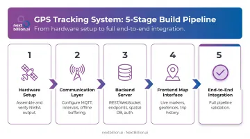
Building this system follows a strict sequence. Skipping any stage creates compounding problems.
Step 1: Prepare Hardware and Establish GPS Signal
Assemble the GPS module, GSM/LTE communication module, and microcontroller. Flash firmware, insert an active SIM with data capability, and mount the antenna in an unobstructed location.
Before writing any software, power on the device and confirm the GPS module locks onto satellites and outputs valid NMEA data strings. Look specifically for the RMC sentence, which carries latitude, longitude, speed over ground, and track angle. No software work should begin until hardware output is verified.
Step 2: Configure the Communication Layer
Configure the device to transmit location data to your backend. Key decisions:
- Choose protocol — MQTT for IoT devices; HTTP POST acceptable for low-frequency prototypes
- Set update interval — balance freshness against data cost using delta-based filtering
- Implement offline buffering — pings captured during connectivity loss must queue locally and sync in batch on reconnection, not get dropped silently
Offline buffering is not optional. Dead zones (tunnels, underground parking, rural areas) are guaranteed in any real-world fleet deployment.
Step 3: Build the Backend Server
Create REST or WebSocket endpoints to receive location pings. Core requirements:
- Spatial database with indexing (PostGIS GiST indexes or GeoHash encoding) — add this from the start, not after you have millions of records
- Authentication — JWT or API keys so only authorized devices write and only authorized users read
- Rate limiting — protects against misconfigured devices sending floods of pings
- Redis caching for latest-known position per vehicle, so dashboard refreshes don't hit the primary database on every update
Step 4: Build the Frontend Map Interface
Render a live map view using a mapping SDK. The frontend needs to:
- Subscribe to the WebSocket feed and update vehicle markers without page refresh
- Draw and monitor geofences with breach alert notifications
- Render trip history as polylines with timestamp scrubbing for replay
Your mapping API choice carries the largest cost impact here. A dashboard updating every 5 seconds across 200 vehicles generates millions of map events monthly.
Step 5: Integrate and Connect End-to-End
Run a complete end-to-end test with a single vehicle before touching the fleet:
- Generate a GPS ping at the device
- Confirm it appears on the dashboard within your target latency window
- Trigger a geofence breach and verify the alert fires
- Confirm trip history persists and replays correctly
Pro tips for production readiness:
- Spatial indexing must be in place before scale; retrofitting PostGIS indexes onto millions of rows is expensive and slow
- Purpose-built fleet tracking APIs like NextBillion.ai's Live Tracking API remove the burden of maintaining custom mapping infrastructure, with route optimization, snap-to-road trip reconstruction, and driver behavior alerting included
- On-premise deployment options matter for teams with data residency requirements — NextBillion.ai supports Kubernetes-based deployment on AWS, GCP, Azure, or bare-metal
Testing and Validating Your Tracking System
Validation before fleet-wide deployment must cover three dimensions:
- Positional accuracy: Drive a test vehicle along a pre-mapped route with known landmarks and compare GPS-reported positions against actual positions. Under open sky, expect accuracy within 7–8 meters for standard receivers and a few meters with WAAS-enabled hardware. Accuracy degrades near buildings, in tunnels, and underground — test in your actual operating environment, not just open roads.
- Data pipeline latency: Confirm the map updates within your target window after a position change. No universal fleet industry standard defines acceptable device-to-dashboard latency, so set your own SLO based on your use case (dispatch vs. customer-facing ETA vs. audit), then validate it under load.
- Alert reliability: Breach geofences and trigger speed thresholds deliberately; confirm alerts fire consistently, not just occasionally.
- Connectivity edge cases: Drive through a tunnel or parking garage; confirm buffered data syncs correctly on reconnection without duplicate or missing records.
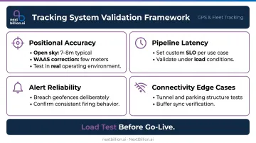
Load testing is non-negotiable before go-live. Simulate the full fleet sending concurrent pings to verify the backend holds up under peak load. The AWS sample project aws-iot-locust-test provides a Locust-based framework for simulating many MQTT clients against IoT Core, which is a practical starting point for this exercise.
Common Challenges and How to Fix Them
GPS Signal Loss in Urban or Indoor Areas
Problem: Vehicles in dense urban canyons, tunnels, or underground parking lose GPS lock, creating position gaps or stale "last known" markers on the map. The root cause is satellite signal blockage with no fallback positioning method.
Fix: Buffer pings locally so data queues during signal loss and syncs on reconnect. For coverage gaps, AGPS (Assisted GPS) can estimate position using cell tower coordinates (Cell ID) and enhanced radio measurements (E-CID) — treat it as a low-confidence fallback, not a substitute for a full GNSS fix.
High Latency Between Device and Dashboard
Problem: Map updates lag noticeably behind actual vehicle position, making the system unreliable for dispatch or real-time ETAs. This usually traces to a polling-based architecture (HTTP GET every N seconds) rather than a persistent connection, combined with unindexed database queries or an under-provisioned server.
Fix: Migrate from polling to WebSocket or MQTT. Add PostGIS spatial indexes. Cache the latest known position per vehicle in Redis to avoid primary database hits on every dashboard refresh.
Excessive Data Costs or Battery Drain
Problem: Devices transmit too frequently, generating unexpectedly high cellular bills or rapid battery depletion. Fixed-interval transmission — regardless of whether the vehicle has moved — is the usual culprit, typically combined with no delta filtering.
Fix: Implement motion-detection logic — transmit at high frequency when moving, drop to a heartbeat interval (a few minutes) when stationary. Apply a distance threshold so a ping only transmits when the vehicle has moved beyond a configurable number of meters.
Frequently Asked Questions
What is a real-time vehicle tracking system?
A GPS-based technology that monitors vehicle location, speed, and movement continuously, transmitting data to a central server and displaying it on a live map. Fleet managers, dispatchers, or customers can see vehicle positions as they happen, enabling dispatch decisions, ETA accuracy, and compliance monitoring.
What components are needed to build one?
Three layers: a hardware device (GPS module + cellular modem + microcontroller, or a commercial telematics unit), a backend server with a spatial database, and a frontend map interface. The exact components depend on whether your deployment is a DIY prototype or a platform-based production system. Production builds also need a routing and mapping API to turn raw coordinates into usable ETAs, geofences, and route corridors, rather than just plotting dots on a map.
What is the difference between active and passive vehicle tracking?
Active systems transmit location data in real time over cellular or satellite networks, enabling live dispatch and monitoring. Passive systems store GPS data onboard and upload it later when docked or connected to Wi-Fi, making them suitable for after-the-fact review or store-and-forward workflows. For US fleets subject to FMCSA hours-of-service rules, active tracking is generally preferred since dispatchers and auditors need current, not delayed, vehicle status.
What communication protocol is best for real-time GPS tracking?
MQTT suits IoT devices with limited bandwidth or intermittent connectivity, thanks to its lightweight publish-subscribe model and low overhead. WebSocket fits server-to-browser live dashboard connections. Most production systems use both in combination.
How accurate is real-time GPS vehicle tracking?
Standard GPS receivers achieve accuracy within 7–8 meters horizontally at 95% confidence under open sky, per GPS.gov. WAAS-enabled receivers can reach a few meters. Accuracy degrades noticeably in urban canyons, tunnels, and dense foliage, and is often supplemented with cell-tower positioning as a fallback.
Should I build a custom tracking system or use an existing platform?
Custom builds offer maximum flexibility but require significant engineering investment: spatial indexing, offline buffering, alert pipelines, and map cost management all need ongoing maintenance. Existing platforms deploy faster and carry lower operational risk, especially for teams that need geofencing, route optimization, and driver behavior monitoring alongside basic tracking. If the project is a proof of concept or a first internal pilot, starting with a platform's tracking APIs reduces upfront risk before committing to a custom build.
Can my car be tracked without me knowing?
Yes, if a GPS tracker is physically installed on the vehicle or if a connected app or telematics device already has location permissions enabled. Commercial fleet vehicles are typically tracked openly as a condition of employment, often disclosed in company policy. For personal vehicles, unauthorized tracking may violate state privacy laws, so drivers should review installed apps, aftermarket devices, and dealer-installed telematics if concerned.
Can a cell phone detect a GPS tracker?
A phone cannot directly detect a passive GPS tracker, since many operate independently of cellular networks and only store data locally. Trackers that transmit over cellular networks may be found using a network scanner app or an RF detector, since they emit signals within cellular frequency bands. Physical inspection of common hiding spots, such as the undercarriage or trunk, remains the most reliable detection method.